
Last Updated on November 16, 2018 by Amit Abhishek
Have you wondered why some vehicles release visible blackish exhaust while other’s not? The darkness or blackish nature of exhaust gases depends much upon the fuel atomization and fuel pump timing. Proper injection at set point of time will lead to complete combustion producing clean exhaust gas; while any deviation in injection timing results in incomplete combustion and thus dark smoke full of shoot and unburned particles.
If remained unchecked; improper fuel pump timing not just cause black smoky exhaust but can also results in too high exhaust temperature, high temperature corrosion and abnormal running condition. A fuel pump timing is nothing but the timing at which fuel is injected into the cylinder. This time is ideally from 10-20 BTDC ( Before Top dead center ) to 10-20 ATDC ( After top dead center ). A TDC is the the top dead center or simply speaking the top most position in cylinder a piston can move to.
To understand why and how to check fuel pump timing in two and four stroke engine; we need to understand timing diagram and working of fuel pump in I.C Engine. The timing diagram represents six major events in fuel combustion in both four and two stroke engine. While timing diagram of two stroke engine shows; aspiration, compression, fuel injection, expansion, exhaust and a brief overlap period. On other hand a two stroke engine have timing diagram representing; scavenging, post scavenge period, compression, fuel injection, expansion and exhaust.
A fuel pump can be manually or electronically controlled as with E.C.U based common rail injection system. The fuel pump irrespective of its type inject a set amount of fuel at desired pressure into the cylinder. let us dig deep into it explaining its need and effects on engine and its performance.
Factors Determining Change In Basic Fuel Pump Timing & Its Calibration
1 ) Timing Diagram
A timing diagram represents the operation of exhaust and inlet valves along with the point of fuel injection on graph. The complete combustion process is represented on graph for the 360 degree rotation of crankshaft; i.e movement of the piston from TDC to BDC within the cylinder space. It is then used to find whether the engine performance is in synchronous with manufacturer recommendation.
Any deviation in injection timing can have adverse effect on engine performance with worst possible scenario; engine running in backward direction for two stroke engine. It is possible as the the two stroke engine have identical timing for scavenging and exhaust with no need for pair of valves to work in sequence to complete the combustion process. Thus it is extremely important to follow the timing diagram provided by the manufacturer.
The timing diagram of a typical two stroke diesel engine engine is:
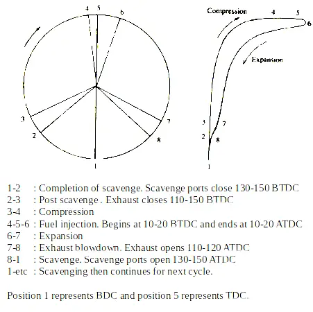 Combustion by product in form of exhaust gas is released in air; through exhaust port from 110-120 ATDC to 110-150 BTDC. In mean time fresh air is taken into the cylinder through the process of scavenging from 130-150 ATDC to 130-150 BTDC. Fresh air is then compressed inside cylinder with fuel being injected from 10-20 BTDC to 10-20 ATDC. Air suddenly expands as a result of combustion pressing piston downwards; with the process the repeat by itself.
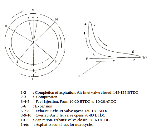
Similarly in four stroke engine the process of aspiration complete with the closing of inlet valves at 145-155 BTDC. Fresh air is then compressed cylinder with fuel being injected from 10-20 BTDC to 10-20 ATDC. Air suddenly expands as a result of combustion pressing piston downwards; with exhaust valve opening at 120-150 ATDC. Exhaust valve finally close at 50-60 ATDC with an overlap period starting from 70-80 BTDC with opening of inlet valve.
 2 ) Working Of Fuel Pump In I.C Engine
A fuel pump supply a definite amount of fuel to the combustion chamber at a fixed time interval irrespective of the load. The pump produce high pressure which helps inject fuel inside the cylinder; against the spring tension in fuel injector. This helps atomize fuel inside with proper penetration to maintain high combustion efficiency. If you don’t know what atomization is? Consider it as a process which breaks fuel into very small particles to mix well with the air.
There are three main types of fuel pump used for internal combustion engine; simple mechanical pump, plunger pump and common rail injection system with electronically controlled fuel injection. A simple mechanical pump is used in old automobile engines with fuel sent to the carburetor; rather than injecting directly to the combustion chamber. The role of carburetor in a S.I ( Spark Ignition ) engine is to produce air fuel mixture at set ratio outside combustion space.
This add up to the time required for the combustion affecting overall process. Thus it is logically replaced or neglected upon superior electrical and mechanical plunger type fuel pumps. An example of plunger type mechanical pump is the bosch jerk fuel pump; while electrical fuel pumps are used with common rail injection system. I have covered in detail about both bosch jerk pump and common rail injection system; along with fuel injector in the topic: Detailed Working of Marine Fuel Pump And Injector.
A ) Bosch Jerk Pump
Bosch jerk pump is simple yet effective design with a single piston assembly known as plunger; that operates in accordance with the cam profile. A helical spring is mounted on top ensure continues contact in between plunger and cam follower. The plunger moves up and down within the cylinder barrel filling it with fuel oil to inject it at high pressure. A helix machined onto it allows to control the amount of fuel to be injected; by changing the angle of helix upon plunger rotation.
The plunger is turned against the barrel position using rack and pinion arrangement. While to change fuel pump timing we have to manually increase or decrease the relative height of plunger. Increasing its relative height advance the injection time while decreasing retard in a subsequent manner. For non VIT ( Variable Injection Timing ) engine we can change the injection timing by adjusting pump shims on base surface.
B ) Electronically Controlled Fuel Injection ( Common Rail Injection System )
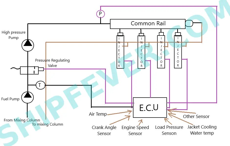
Unlike mechanical fuel injection system; a common rail injection system use a central high pressure fuel pump for each cylinder. These high pressure pumps are conventionally operated mechanically via engine movement; but newer designs also come with electrical driven pumps for small automobile engine. While diesel engine use common rail injection system petrol engines use gasoline direct injection. The common point among them is that; in both the fuel injection is electronically controlled by a Central control unit called E.C.U.
Common rail injection system use pair of central fuel pump to pump fuel oil to the common rail. the typical pressure range for common rail is 1000 bar to 1800 bar; but can vary from engine to engine. A central electronic control unit take signal from various sources including; air temperature, crank angle, engine speed, load, jacket water temperature and fuel pressure to maintain correct fuel pump timing. Thus the E.C.U or electronic control unit of a common rail injection system can be programmed to change injection timing.
This in turn provide the option to change the entire E.C.U or its specific parts rather than sending it for reprogramming to change fuel pump timing.
Effects Of Fuel Pump Timing On I.C Engine
Why we should check whether the engine fuel pump timing is as per the manufacturer recommendation or not? The time of fuel injection in an engine can change due to a number of reasons including; fuel pump timing, faulty or broken injector spring and poor fuel quality. Any deviation in the fuel injection can have adverse effects on engine from heavy vibration and shock load to the loss of energy, incomplete combustion and high exhaust temperature.
There are others visible symptoms such as trouble starting, black smoke, abnormal engine behavior, engine misfire with sudden increased in combustion of fuel. If remained unchecked it not just cause pollution, hot corrosion and overheating of parts; but will take the engine to unsafe stress level with high risk of unintentional reverse rotation of engine. This is why its common practice to check for the fuel pump timing; in case of any deviation in the time of fuel injection.
Effects of Injection Timing On Engine Performance:
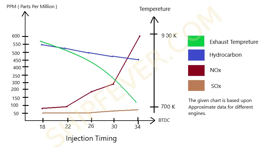 For a typical I.C Engine the amount of Nox emission increase drastically with early ignition which means fuel is injected earlier in BTDC. Similarly the amount of SOx emission also increase a bit after 20-26 BTDC ( Too early Ignition ); which usually depends mostly upon the amount of sulphur in the fuel. By contrast the amount of hydrocarbon generated by the engine decrease with the time of ignition; earlier the ignition lower will be hydrocarbon generation.
While engine peak pressure and exhaust gas temperature tends to change in opposite manner with respect to injection timing. Exhaust temperature increase with retarding injection timing while peak pressure increase for advancing injection. Similarly exhaust gas temperature increase gradually from early ignition towards late ignition due to change in fuel pump timing. There is a sudden increase in peak pressure for a small degree change in fuel injection timing.
There is a no doubt that injecting fuel oil early into cylinder increase the power, its efficiency and thrust at the cost of shock load, high vibration and higher level of Nox emissions. On other hand retarding injection timing reduce engine performance, increase exhaust gas temperature and make the engine operation uneconomical. Thus it is important to keep the injection timing within a limit recommended by the engine manufacturer.
How To Check For Wrong Injection Timing
The best and easiest way to find if there is possible deviation in fuel pump timing is to take draw card diagram. To take the draw card diagram place the indicator instrument to the indicator cock; with the indicator drum out of phase of the piston stroke by 90 degree. It helps measure the change in pressure during the complete combustion process; and thus check any deviation in compression and maximum pressure due to fault.
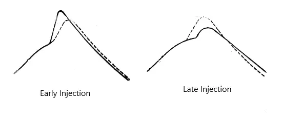
Take the draw card diagram and compare it to that of normal or recommended diagram by manufacturer. Any sudden peak in maximum pressure or slight increase in compression pressure; with delayed and small spike in maximum pressure is a sign of early or late fuel injection. Once known of any deviation; confirm it using hair line method. Hair line Test is a method of checking fuel pump timing by looking for the crank angle when the marking on plunger and its body coincides.
When the unit is at TDC with both markings on plunger and its body coincide; the crank angle marking on flywheel will tell the exact position of fuel injection on timing diagram. For small single cylinder engines we can do the same with timing pin method. Remove the Timing pin bolt cover and turn the crankshaft till the timing pin set into the notch of camshaft for the fuel pump. Then insert the threaded bolt into the pin hole to check if it is going smoothly.
If the bolt goes smoothly down into the pin hole the fuel injection timing is correct else we need to do corrective adjustments.
How Can We Adjust Fuel Pump Timing
Since we already knew about the incorrect fuel pump timing it won’t be hard to fix it. Fuel pump timing can be adjusted by simply adjusting number of shims to the pump base. Add or remove required shims to set required injection timing. For some engines you may also required to manually adjust the relative position of cam with respect to crankshaft to do the job. It is generally accepted to set fuel pump to start injection at 15 degree BTDC.
For Vit engines the fuel pump timing can be easily set by; adjusting the relative height of plunger with respect to the barrel. One can retard the injection by lowering plunger and advance by increasing its height / relative position. Or you can follow the old method of changing the position of cam with respect to its shaft. Turning the cam in the direction of normal camshaft direction will advance the injection; while turning in opposite direction will retard it.
You can easily fix the incorrect injection timing in a electronically controlled injection system; such as common rail by programming or recalibration of E.C.U. There are also spare programmed chips are available on ship and industrial complex with big engines; to simply replace it with spare ones in case of doubt and confusion. But generally reset or recalibration do the job and there is no need to either change or program the E.C.U.
Note: This article is produced on Request from Russel Devotta.
Also Read:
- Relay – Its Application, Parts And Function
- How Do Flywheel Work & Its function In I.C Engine
- How To Measure Wear Ring Clearance In Centrifugal Pump
- What are BFP ( Boiler Feed Pump ) – Parts & Working
- Engine Cooling System – Types And Their Working