

Last Updated on June 30, 2020 by Amit Abhishek
Flammability diagram or flammability composition diagram is one of the important documents used across the world to understand and prevent fire and explosion. They are mainly used for the hydrocarbon mixture and so a key to the cargo and ship’s safety on tankers.
It is essential on-board to follow certain procedures based on the studies from the flammability graph of the hydrocarbon mixture.
Flammability diagram explains to us how a gas or mixture of two gases will behave and catch fire with dilution other gas or air.
They are also sometimes called a ternary diagram as it represents flammability range in the mixture of inert gas, oxygen (air), fuel, and nitrogen represented on a triangular diagram.
Fire ( Basics )
Fire safety is the key to the successful operation of industries including shipping. A detailed discussion and planning are required on tankers ( A type of ship ) to avoid any mishap. Proper tank cleaning, loading, and discharging produce to be followed to avoid fire and explosion.
It needs only air, heat ( source ) and fuel to start a fire. These three components are always available onboard ship, and risks are high with tankers.
On tankers fuel is always present in large quantities in different holds, the air is present everywhere and the heat source can be from hot work to a spark due to static discharge. removing any side of this fire triangle ( Air, Source, Fuel ) we can prevent fire on-board.
Inert gas is used on-board to remove the one side of the fire triangle i.e air; by pumping in inert gas in tanker holds to keep oxygen level at a minimum. Flammability diagrams are used to understand the tank’s atmosphere and help predicts; how much oxygen to be maintained at all times.
Flammability Diagram
The flammability diagram is the key element for planning safe cargo operation onboard ship. the diagram itself varies for different hydrocarbon gases; so we must understand how to read and understand it.
For example, we get the lower and upper flammability limit of 1% to 10% based on the Flammability diagram for crude oil.
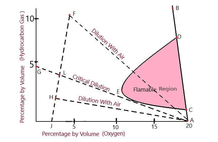
Here, line AB represents the mixture of oxygen ( Air ) and particular hydrocarbon gas. Anything that is left to the line AB represents the condition where inert gas is also mixed with the hydrocarbon-air gas mixture.
The gas mixture represented by AC on line AB is too lean to catch fire while DB is too rich mixture to get fire.
Now according to the diagram, When we go left to the line AB ( Add inert gas to the tank’s ) there is a sudden change in tank atmosphere.
Similarly, the upper and lower flammability limits changes with more and more mixing of inert gas. Finally, the upper flammability limit ( The maximum amount of hydrocarbon gas to air mixture which can sustain fire) and lower flammability limit (The minimum amount of hydrocarbon to air gas mixture which can sustain fire ) meet at a point, represented on the diagram as Point E.
What is Lean or too Rich mixture?
In a hydrocarbon-air gas mixture; when it is too rich in fuel to burn is known as a too-rich mixture. Here the amount of oxygen required to sustain the fire is absent making it impossible to catch fire. Such an atmosphere can be easily tested on board by using Tankscope.
On another hand when the amount of hydrocarbon-air gas mixture is too lean to catch fire; the mixture is called a lean mixture. On-board a special equipment called explosimeter is used to detect the presence of hydrocarbon in such an atmosphere.
Understanding Cargo Operation on Flammability Diagram
Inert gas is pumped into the tanks while and after the successful cargo operation. On the flammability diagram, it can be seen as the decreasing gap between the UFL ( Upper flammability limit ) and LFL ( Lower Flammability limit ). The UFL and LFL meet at point E; but inert gas is pumped in until it reaches to the point F represented on the diagram.
Now during cargo discharge, if the tank atmosphere is diluted with air (Oxygen); it will follow a dangerous path FA. From the diagram itself, we can see that the path FA pass through the flammable range and so can be hazardous. So to avoid such a scenario; inert gas is purged into the tank before and during the cargo operation ( Discharging ).
By purging inert gas into the tanks, Oxygen-Hydrocarbon mixture is taken to point H from F. Now any further dilution with air while discharging won’t cause any risks to the ship; as the line HA represented on the flammability diagram don’t pass through the flammable range. Now suppose for some reason the tanks are filled with less inert gas than required. Then during discharging it will miss the flammable range by a small margin.
On the flammability diagram, it can be seen as line GA; which goes almost touching the flammable range. This is called the critical dilution; the minimum amount of inert gas required to ensure the hydrocarbon mixture don’t go into the range of flammable reason.
Conclusion
Flammability diagrams are an important document used to prevent an explosion onboard ships. An explosion can occur within the boundaries of the flammable zone in the diagram.
So it’s important to know and understand the diagram to prevent fire hazards. The flammability diagram shows us that; the presence of inert gas in the cargo holds don’t guarantee safe cargo operation.
Unless the amount of inert gas is always above the critical dilution limit. It is well understood that any amount of oxygen below 8% in the hydrocarbon-air gas mixture is not a threat. But to ensure the proper safety of the ship; it is kept at 5% at all times.
Note: I have tried best to answer your queries. But still, if you have any doubt; don’t forget to comment down below!
Also Read:
- Helpful Guide On Crankcase Explosion | Cause Action & Safety
- List of Hazards Associated With Petroleum Products
- CO2 Flooding System – Fixed Fire Fighting System Ship
- Oil Tankers In Detail – Types, Sizes, Construction
Flammability diagram mainly used for gas freeing a tank for Man Entry.
It should be mentioned somewhere in notes.
In the diagram Flammable Mixture is called as Flammable Reason.
Some proof reading before publishing will go a long way
In the diagram and elsewhere the Flammable reason represents the concentration of Air + Fuel mixture which is cable to burn. So yes that reason is of the flammable mixture which can be ignited. There is no confusion, they are just different way of explanation. Here flammable Region represents flammable mixture; Just like in many books instead of flammable mixture they use Explosion or Explosive Region / Flammable etc. I hope i solved your concern, anyway thanks for letting us know of your view on the topic.
He is saying replace, reason with region.
Understood, Thank you for letting us know of the spelling mistake. It’s been rectified!
thanks a lot..keep up the great work.
Thank you, this explanation is very helpful.