
Last Updated on November 17, 2018 by Amit Abhishek
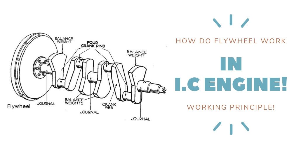
A flywheel is nothing more than a heavy mechanical device attached to the shaft to store surplus rotational energy. It acts as a rotating reservoir which store energy; when its available in abundance and release when most needed much like a battery. It has a significant weight in respect to the crankshaft assembly; and thus helps maintain torque resisting rotational speed. They are generally installed in system’s with varying load and fluctuating torque; as in internal combustion engine.
Due to its heavy weight a flywheel have very high inertia causing it to; remain at the same speed irrespective of the opposing forces. The energy stored to these flywheel are proportional to their square of rotating speed. A torque is applied to the flywheel to store rotational energy and when needed; energy is released from flywheel in the form of torque applied on the mechanical load. Thus it increase its rotational speed while storing energy and loose while releasing it.
You can understand its application in daily life with a simple example. Remember your childhood toy which you used to play rubbing across the floor to run. Such small cars are simple examples of flywheel in action; mechanical energy is stored in their flywheel when rubbed across the floor which then they released once set free. Some others examples of flywheels in daily life are automobile engines, sewing machine and manual sugarcane juice extractor.
What Are Flywheel & Its Types
A flywheel is in existence since the dawn of industrial revolution. Back then it was purely mechanical with a wheel attached to the axle; it doesn’t change much right? These days flywheel are more of a complex arrangement sitting on one side of the shaft; to transfer energy to and from the engine / source. They are no longer just limited to simple machines and engine but are used in many other applications. For example in power grid for frequency regulation, in rails for transit power recovery and mining; to store waste energy reducing overall fuel consumption.
It’s working can be summarized and understand with the following physics equation: torque on axis of rotation = I.α . When an body rotate freely at a fixed axis; then a torque ‘t’ is required to change its motion with an angular acceleration ‘a’. The required torque is then proportional to its angular acceleration; and is given by the product of its moment of inertia and angular acceleration. We will discuss in details about its working principle later in this post.
Based on its mass it can be either a single mass type or double mass flywheel. A single mass construction is cheaper; moderately dampen engine vibration and can withstand greater heat capacity. They are made of cast steel and have nothing in between themselves and clutch assembly. A single mass design is constructed for flywheels with multipurpose application; such as energy storage, vibration dampening and power recovery.
On other hand a double mass construction is made specially to dampen vibration and noise. They have a spring in between the two flywheels as an dampener. Both flywheels can move independently to each other within a fixed limit. These design are expensive and are prone to damage under high temperature or rough use.
Why Flywheels are Used in I.C Engine
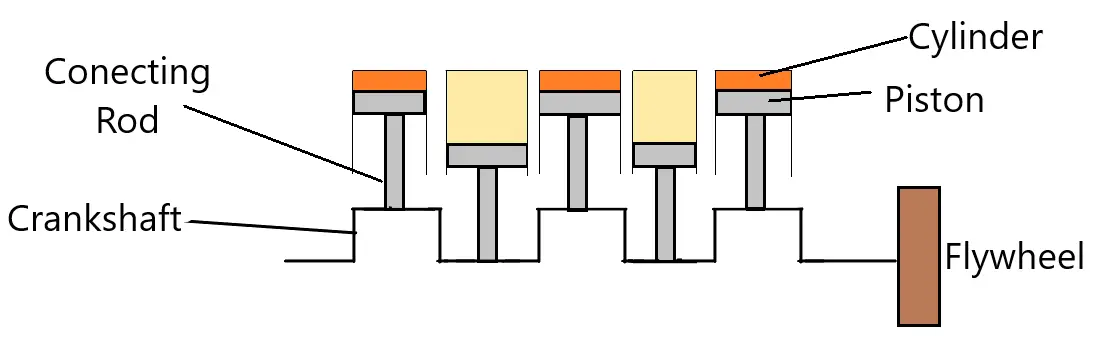
I believe we all understand the basics of how I.C engine works. For those who don’t; an I.C ( Internal Combustion ) engine is a heat engine type where fuel is burned within a confined space called combustion chamber. They are generally rotary or reciprocating engine with a piston assembly. Sudden expansion of flue gas after combustion move the piston downwards; which in turn rotate the crankshaft and finally the vehicle / output shaft.
Combustion took place only once every four cycle in four stroke engine; while every two cycle in two stroke engine. So power is available for only one cycle; this doesn’t mean the engine should work for that one cycle in two & four stroke engine. This is when a flywheel comes handy as it seamlessly provide power to the crankshaft at all times; keeping engine moving. A flywheel is connected directly to the crankshaft end; maintaining consistent power and orientation of the engine.
Thus flywheels help ensure consistent power delivery in single cylinder engine. But multi cylinder engines can be timed to have consistent power delivery; yet still we have flywheels in those engine. But why? In multi cylinder engine they are used to control engine vibration; balance crankshaft; ensure proper running direction and crank engine when required. Multi-cylinder engines have even output torque and thus require smaller light flywheels; that add up to engine acceleration.
Working Principle
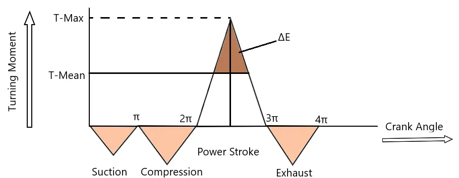
The turning moment of a four stroke engine for different position of crank is only positive for the power stroke. As we have discussed earlier; an I.C engine produce power only during the power stroke. From the turning moment diagram we can see that; during suction there is negative turning moment due to cylinder pressure less than 1 atmosphere.
Similarly energy is taken from the crankshaft and flywheel to do work on the gases; which results into a much higher negative turning moment. Then during the power stroke we see a surge in positive turning moment; due to the expending flue gas pressure. While during the exhaust stroke flue gas are released by working onto the gas; resulting into a negative turning moment.
From the given turning moment diagram; one can clearly see the torque / turning moment generated is much more than the mean torque. So there is this extra torque generated during the power stroke; which need to be stored and then released using the flywheels. The energy stored by a flywheel with a very thin rim and mass “m” can be given by:-
E = 1 / 2 X I ω2
Where ‘ E ‘ is the mean kinetic energy of the flywheel. ” I ” is its moment of inertia and ” ω ” is its angular velocity. Now since during the suction, compression and exhaust stroke; energy is taken from the flywheel; and added during the power stroke.
So the kinetic energy of the flywheel for the fluctuating angular velocity will be:-
E = Maximum Kinetic Energy – Minimum Kinetic Energy = Work done by torque on flywheel ( Proof on Brilliant.com )*
Or,
E = 1/2 x I x ( ω1 + ω2 )( ω1 – ω2 )
Now since ( ω1 + ω2 ) / 2 = ω
Therefore,
Now since, ω = 2πN / 60
Therefore,
Where, K is the radius of gyration for the flywheel.
Now, Energy stored in the flywheel can be given by:-
Where; Cs is the coefficient of viscosity for the flywheel i.e (N1-N2)/N
How Can We Use Flywheels To Determine Running Direction?
A flywheel can be little handy determining the running direction of an engine. You can simply tell which way the engine is rotating; giving a look at the engine flywheels. It is so because a flywheel don’t have its own rotational direction; but rather follow the engine direction on which it is mounted. When looked from the flywheel end; if it rotates clockwise then the engine is a right hand type. Similarly if the flywheel rotate anticlockwise in an engine its a left hand type.
In multi cylinder heavy engine such as in industries and ship; these flywheels can also be used to determine piston position in cylinder. Using the cylinder markings on the flywheel you can know in which cylinder the piston is at T.D.C. This can then be used to determine firing order of an engine. If the engine is stopped for long and need to be purged; these flywheels come really handy. To purge an engine you need to rotate the flywheel either manually or through a motor with indicator cock open.
Although an engine can rotate in both clockwise or counter clockwise direction; but generally most engine rotates in counter clockwise direction. But it’s not a set rule as its just a matter of designer’s choice to prefer one over the other. So you must always knew the correct running direction of an engine; either through the engine manual or visually inspecting its flywheel.

Common Flywheel Doubt’s & Their Answers
Q.1. Why flywheels only made of cast iron?
Ans: You might have read in many manuals or on web that this flywheel is made of cast iron or Grey cast iron. It may arose doubts whether all flywheels are made of cast iron or at least most of them. In fact a flywheel can be made from different material; depending upon the application. Very small flywheels as such in toys are made mostly from lead. Medium or small flywheels can be of cast iron, aluminum or steel. But the big flywheels are made of cast iron or high strength steel depending upon the needs of the design.
Q.2. Why Flywheels have Teeth?
Ans: Not all flywheels have teeth but most flywheel on cars, motorcycles, heavy generators and ships have teeth; but why? Since you know flywheels help maintain constant power output; but how we get that output if we won’t start the engine. If you had or have a motorcycle you must known how we need to kick or self start to run the engine. What actually it does is that it rotate the flywheel through a small gear attached to the flywheel teeth. In large diesel engine such as in ship where compressed air is used crank or start the engine; these flywheel teeth are used for high pressure fuel and servo oil pump.
Q.3. Are flywheel and Governor Similar?
Ans: Both flywheel and a governor is used to regulate engine speed; but in a different way. On one hand flywheel regulates the speed of an engine over different strokes; to keep its mean speed constant. But a governor is used to regulate the mean speed of the engine for variable load. This is achieved by adjusting fuel injection to meet increased power demand. when sudden load increase; the engine start to slow down. Now to keep the engine speed constant; governor increase the fuel injected into the cylinder to generate more torque and thus increase its speed. So although both flywheel and a governor seems to do similar job but are really different.
Also Read:
- Why Does A Ship Float At Sea But Sinks In River?
- Why Do A Fan Have Capacitor ? – Explained
- Boiler Mountings And Their Function – Complete List
- What are BFP ( Boiler Feed Pump ) – Parts & Working
- Scavenging In Two Stroke Engine – Types, Advantage & Use
Can’t Find What You Are Looking For?
Why not Request your own Topic !
Note: *( External link to brilliant.com is only to assist you understand the concepts; & we are not responsible for content on that site. Please read our Disclaimer and privacy policy for details ).
Comment…
nice corverage
Thank you, I am running my last year and prepare for engine cadet later on.