The indicated power of an I.C engine is the total power developed within the cylinder in one complete cycle neglecting any losses. It is the sum total of the brake power and the friction power of an engine.
In short it is the maximum power available from the expanding gases developed by combustion of fuel within the cylinder; neglecting frictional losses, mechanical losses and loss due to heat and enthalpy.
Which means this is the theoretical maximum and actual power developed within the cylinder that never reach completely to the crankshaft.
You can measure the indicated power of an engine by using the indicator diagram or power card diagram. An Indicator diagram is taken to access the performance of each cylinder unit for an engine.
The indicated power of an engine can change under varying conditions. Thus indicator diagram for an engine or particular cylinder is taken at a particular frequency or RPM. This can then be mechanically represented as:
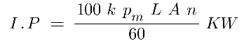
Where,
k = Number of cylinders or factor ( 1 for 2 stroke and 1/2 for 4 stroke )
Pm = Mean effective pressure in bar.
A = Area of the piston in meter square.
n = Rotational speed of the engine or RPM speed.
L = Length of stroke in meters,
Difference Between Indicated Power And Brake Power?
As described above indicated power is the power of an engine developed in cylinder. It is the sum of the power produced at the crankshaft and consumed by the friction and heat losses.
A part of this indicated power is consumed in overcoming the friction of various moving parts and some lost as heat via cylinder walls and exhaust. Thus indicated power is evaluated based on the combustion efficiency of that particular cylinder.
The brake power on the other hand is the power available at the crankshaft for the actual application.
Large brake dynamo-meters or any other brake mechanism is used generally at the manufacturing facility to determine the torque and angular velocity of the rotating output shaft.
Based on their working these braking dynamo-meter are too classified into two main types; Absorption Dynamo-meters and Transmission Dynamo-meters.
Now since brake power is always less than the indicated power. Mathematically you can say this as it is the result of indicated power minus the friction power. This can then be mechanically represented as:
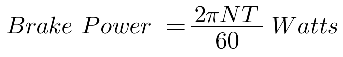
Where,
N = Speed of the engine in RPM
T = Turning moment which can also be given by W x L. Where W represents the brake load in newtons and L represents Length of arms in meters.
How Indicated Power is Measured For Marine Diesel Engine
To find indicated power of an marine diesel engine for a unit we need to first take the indicator diagram for the unit. Then we need to calculate the area of the given curve diagram.
An indicator diagram is recorded on ships using a special instrument called an “indicator instrument“. Which consists of a small piston locked within a cylinder acting against a calibrated spring.
The instrument itself can be used to draw all major types of indicator diagrams used to study and rectify engine parameters.
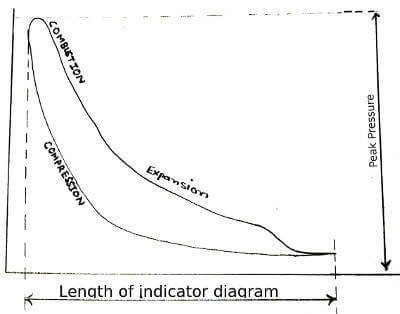
This can be then used to determine total power generated for the engine; compression pressure, peak pressure and efficiency of the engine. Similarly, any deviation in the diagram helps us know of any irregularity in fuel injection and conditions of running gears.
To measure, the indicator instrument is placed on the indicator cock with its drum in phase with the piston movement. The P-V diagram ( Indicator Diagram ) illustrates the variation of cylinder pressure; concerning the piston movement.
The area of the diagram is calculated using a planimeter/platometer and then multiplied by the cylinder constant and the engine speed.
Correct Procedure / Steps To Take Indicator Diagram
- Prepare the indicator valve and the indicator instrument for taking the reading.
- In the case of digital indicator make sure your data acquisition unit is fully charged and functional.
- Take full safety precautions with appropriate PPE ex: high-temperature gloves, hard hat, eye protection, etc.
- Keep the engine running at a constant speed.
- Operate the indicator cock with care and make sure the line is clear of any shoot particle before use. ( Do a short blow through )
- Dismantle the upper part of the indicator instrument before mounting to ensure its various recesses are clean.
- Fit the indicator and cord in a firm tight position.
- Now engage the indicator drive and check for alignment; so the diagram is traced in the middle of the paper/sheet.
- With the indicator cock shut press the stylus against the paper to draw the atmospheric line.
- To draw the indicator diagram release the cord from the indicator drive and slowly open the indicator cock.
- Press the stylus slightly against the paper while pulling the roller string as it traces the diagram on paper.
- Close the indicator cock and remove the instrument.
- Check that the diagram drawn is correctly visible and distinct.
Approximate Indicated Power For Multi-Cylinder Engines ( Morse Test )
Indicator diagram is used to find the indicated power of a unit/cylinder; but how would you find the indicated power for a multi-cylinder engine? Thus morse test is used to determine approximate total indicated power.
The whole method is based on simple fact that when one cylinder is made inoperative the brake power for the engine get reduced by one cylinder output but the friction power remained the same.
Thus by making each cylinder inoperative by cutting the fuel supply we calculate the difference in their outputs that determines the indicated power for that cylinder and add them to obtain total indicated power for an engine.
The indicated power for n cylinder can be represented as,
ipn = bpn + fp
Now indicated power for n-1 cylinders can be represented as;
ipn-1 = bpn-1 + fp
Now since we are running the engine at a constant speed. The fp must be reasonably constant over the process for n-1 cylinders.
Thus from subtracting two above mentioned equation the indicated power for the first cylinder can be given as:
ip1 = bpn +bpn-1
ip2 = bpn +bpn-2
And so on for Ip3, 45678. Then the addition of these indicated power will give us the approximate indicated power of the engine.
I.P = Ip1 + Ip2 + Ip3 +…. = Σ ( ip )k Where, K= 1 to n
Also Read:
- Difference Between two and four-stroke Marine Diesel Engine
- Marine Diesel Engine – Parts And Functions
- Common Engine Troubles In Marine Engine | Reason & Cure !
- Why And How To Check Fuel Pump Timing in I.C Engine