

Last Updated on May 19, 2020 by Amit Abhishek
Various propeller and rudder types are used in different ships; all for the same purpose to steer and propel the ship. A propeller is a big fan like structure that rotates to provide required thrust to move the ship; while a rudder is a flat piece of metal at the stern of the ship to steer.
In the first half of the article, we will discuss propeller, its geometry, types, efficiency, and maintenance. While in the second half we will learn about rudders, its types, and use on the ship.
What Is Propeller? ( Basics )
A propeller is a mechanical device with blades that spins around a shaft to produce necessary thrust to propel the ship. The propulsion system with shaft, engine, and propeller moves the ship based on Newton’s third law of motion. The propeller pushes the water backward while the water around pushes the ship forward with equal force.
No matter how much development has happened in propeller geometry. Today a conventional propeller is still the sole force of ship propulsion. Nowadays a ship can have one two or even three propellers not just in numbers but types too. It depends upon the needs for speed, power, draft, and efficiency of the ship.
Construction Material
Marine propellers are made of anti-corrosive materials such as aluminum bronze or manganese bronze alloys to avoid corrosive conditions at sea. Apart from them; alloys of stainless steel and nickel are also used to construct marine propellers. Generally, aluminum-bronze alloy is preferred over others due to its lightweight and good strength.
A typical propeller is made up of Nikalium ( Aluminum-Bronze ) and has elements in composition; Aluminum 9.1%, copper 80.4%, Nickel 5.3%, Iron 3.5%, and Manganese 0.7%. A propeller is constructed by adding blades to the hub. A forged construction is reliable and has better strength but avoided due to high cost.
Propeller Geometry
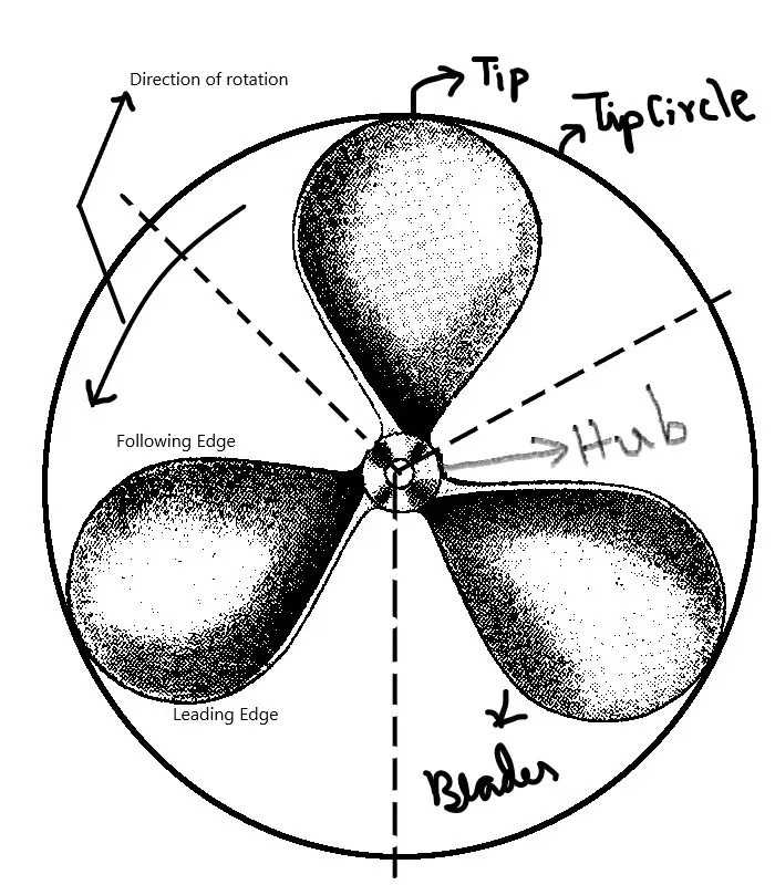
Before understanding propeller types, working, and efficiency we must understand the basic points of propeller geometry. The key points of propeller geometry are:-
1.Hub
A solid circular disc at the center which holds the blades and mates with the shaft. The strength and thrust produced by the depend on size/Diameter of the hub. Smaller the diameter, higher is the thrust produced with lesser strength. So an optimum diameter is chosen to get the maximum thrust at maximum possible strength.
2.Blades
These are the twisted fins like structure attached to the propeller hub. The torque produced by a ship propeller depends upon the shape and driven speed of these blades.
3.Face of Blades
The front side of the blade that faces aft towards the ocean when the ship moves forward. This is what pushes the water backward to create necessary equal and opposite force to push the ship forward.
4.Blades Root and Tips
The part of propeller blades that are attached to the hub is called blade root while the farthest point on the blade edge is called Tip.
5.Leading & Trailing Edge of Propeller Blades
The side of the blade that cuts through the water is known as leading-edge; while the other side is called the Trailing edge.
6.Diameter
The thrust generated by a marine propeller can be determined by studying its diameter/radius. Larger the diameter higher is the thrust produced with better propeller efficiency. But after a certain point increasing diameter can increase unwanted propeller drag.
7.Propeller RPM
It is the number of a revolution that a propeller made during an interval of one minute. Generally on cargo ships; propeller with low RPM and bigger diameter is chosen for higher thrust with better efficiency. On the other hand, high-speed vessels that require much less thrust; need smaller diameter with high RPM propeller for better efficiency.
8.Pitch
It is the imaginary distance the propeller would move forward on the shaft in one revolution. I called it imaginary distance as the propeller never moves forward on shaft; instead, push the water backward. So if a propeller has a nominal pitch of 20 inches; it indicates that it would have moved ( Imaginary ) to an inch on the shaft in one revolution. And the distance between this imaginary distance and actual displacement of the ship is called slip.
9.Left Hand / Right-Hand Propeller – What’s the difference?
When watching propeller from aft; a propeller that rotates clockwise while moving the ship forward is a right-hand propeller. While the one that moves anticlockwise is a left-handed propeller. The left or right-handed propeller is decided on the time of design, so it should never be exchanged with one another. Generally, ships are fitted with right-hand propellers unless it’s necessary.
Understanding Propeller Efficiency
In simple terms, propeller efficiency is the ratio of its output power to its source power. In marine propeller or any other propeller; the source power is the power given by the motor /engine through the shaft. On another hand output power is the ability of propeller to produce a given thrust at a given RPM.
Mathematically it can be given by:-
η =(TXV)2πNQ
Here;
T = Propeller Thrust
V = Mean Flow Speed
N = Revolution per second
Q = Torque produced by the propeller shaft
Geometrically this can be represented as:-
Factors Affecting Propeller Efficiency
The key factors that affect propeller efficiency are:-
1.Propeller Diameter
There is an increase in thrust produced and efficiency with an increase in propeller diameter. On another hand speed or RPM reduces with an increase in diameter; which also aids in increasing efficiency. Generally a balanced is maintained in-between speed, draft, and efficiency according to the ship’s demands.
2.RPM
RPM or Revolution per minute of a ship must never coincide with the resonant frequency of the propulsion system. The thrust decrease with an increase in RPM and efficiency decreases by 15% for each 10% increase in RPM.
3.Blade Area
The area of the blade is an essential component to be considered during the propeller design. Research has shown that, with a decrease in the blade area; there is an increase in propeller efficiency. But during construction, an average of strength and area is decided for overall efficiency.
4.Number of Blades
Research has shown that the efficiency of propeller decrease with an increase in the number of blades.
5.The ratio of Pitch / Diameter
The maximum efficiency for a propeller design can be obtained by finding an optimum pitch to diameter ratio.
Types of Propeller
Propellers can be classified into various types based on two factors; Number of blades and pitch.
Classification on the Basis of Number of Blades
There are propellers with three, four, or even five blades. However, the three and four-blade propeller are the most popular designs used in ships. Propeller efficiency generally decreases with an increase in the number of blades. The different propeller types based on the number of blades are:-
1.Three Blade Propeller
One of the most common propeller designs used in ships. These are made up of aluminum alloys and are preferred for their low cost and high efficiency. The only problem associated with three blades propeller is that; they have more drag and vibration at low/slow speed.
2.Four Blade Propeller
These are the top choice for ships looking for propellers with good strength with the highest possible efficiency. These propellers are generally costlier and made up of stainless steel alloy. They are the best match for ships going for all kinds of water; including rough sea conditions.
3.Five and Six Blade propellers
As per the name; these propellers have five to six blades attached to the hub. They are costlier and have the highest strength of all. Another benefit that made it favorable to use over others is that; it produces less drag and vibrations.
Classification on the Basis of Pitch
1.Fix Pitch Propeller
They are the propeller types with blades permanently mounted to the hub. These propellers are generally cast and so have fixed pitch. They are quite reliable, simple, and robust in design. These propellers are preferred in merchant ships due to their simplicity, low cost, and better efficiency.
2.Controllable Pitch Propeller
A controllable pitch propeller is one whose pitch can be altered for variable thrust load. Propeller blades are rotated along the vertical axis with the help of the pitch of the propeller. They are well known for increasing engine efficiency, smooth maneuvering, and no need for reversing arrangement/gear in the propulsion system.
This means the speed and direction of a ship can be altered anytime without changing the direction or speed of the engine/shaft. They are best suited for ice breakers, tugs, trawlers, and ships which require better maneuverability.
Propeller Maintenance
Regular checks and repairs are to be done on marine propellers in dry dock. These checks are repairs include:-
- Check for any physical damage to the blades.
- Check for cavitation
- Signs of cracks to be looked for
- Polish propeller surface
- A silicone coating is also applied occasionally after polishing.
- Remove Slags
- All other welding and repair work to be done.
Rudders

Q. What rudder means and what do they do?
What rudder is? Is it a wooden block at the back of a ship or some kind of fin? Actually, a rudder is a wooden or metallic flat structure that helps steer the ship. In other words, it can be called a control device fitted on boats, ships, and submarines; that push the water on one side producing required thrust in the steering direction.
They are not just big but large hollow masses; so they not only help steer but also give additional buoyancy. They are coated with special anti-corrosive solutions from both sides with a drain plug provided to remove water if any.
Rudder Types
A rudder can be classified on the basis of its design and construction. On the basis of design; It can be conventionally classified into the following three types:
1.Balanced
These are the rudders that have 30-40% of its area forward to the rudder stock. Here the torque required to turn / move is quite low as it lies on the center of gravity.
2.Semi-Balanced
One of the most used and common rudder types. They have about 15-20% of its area forward of the rudder stock. They are preferred as they provide low steering torque with less counterweight required than the unbalanced types. Actually it is the economical option between the unbalanced and balanced rudder.
3.UN-Balanced
These are the ones with rudder stock attached at the forward position of the rudder as per design. They require the maximum torque to turn the ship but have the benefit of no counterweights required as per design. Experience and experiments have shown that both UN-balanced and balanced rudders are not suited for heavy running as in the case of merchant ships.
Rudder types based on Construction
1.Fully Fabricated
In fully fabricated construction, two plates are fabricated and then joined to webs and vertical / Horizontal strips by welding. The plates are also welded to one another after they are fabricated. This is a commonly used construction method for rudders with reliable and efficient output.
2.Cast Frame
In this kind of construction, a rudder is formed by welding small frames together. Then sides are welded with closing plates. Drain holes are then provided and checked for any welding faults. This is another popular way of constructing a rudder in a cost-effective way.
Q.What is rudder stock?
Attached to the helm; a rudder stock is a cast / forged vertical arrangement hinged to the sternpost. In simple words; it is a vertical shaft that attaches rudder with the ship. It comprises of upper, middle, and lower-end area. The lower end area possesses a nonmetallic tube structure which prevents rudder stock from uneven bending stress/load.
Rudder Trunk
It is a tube-like nonmetallic enclosure that surrounds the rudder stock. They are watertight from the top and left open and exposed from the bottom (as per rules). The watertight glands are fitted at the top with a small opening for inspection. The trunk is kept at minimum length to avoid unsupported rudder stick for long-distance.
Jumping clearance is taken in the dry dock which is a part of propeller clearance from rudder trunk in between carrier and stopper bearing. This measurement is many a time co-inside with the rudder drop the distance between the marked line and the carrier.
Q.What does Rudder Drop Really Means?
It is the measurement of any wear in the rudder carrier bearing. It is measured by getting the difference between a marked line and carrier; but it many a time coincide with jumping clearance ( the difference between stopper and carrier bearing ) measured by a trammel gauge ( L shape Instrument). Basically the difference between the two bearings is measured during the construction of a ship; any change in that value is known as rudder drop.
Also Read:
- Types of Ships and What Do They Do!
- Difference Between two and four stroke Marine Diesel Engine
- Steering Gear System in Ships
- Hydrophore System in Ship
- Flammability Diagram And Its Application in Tankers