
A screw pump is a subset of positive displacement pump that use one or more than one screw; to perform pump action along its spindle axis. The complete assembly consists of two main parts; the driving motor ( prime mover ) and the pump assembly. The motor provides the necessary rotary motion to the pump drive screw coupled to its shaft; which combined with low clearance in between screw create suction pressure.
With better suction capabilities and low maintenance for the same range of speed; it is also regarded as the most reliable pump for a variety of operation. A screw pump is known for its low turbulence, ease of use with high viscous fluids, low vibration; self primed and ability to work with minimal air pocket in fluid with low operating noise.
Screw pumps are best suited for application such as; fuel transfer, high pressure fuel injection, lubrication and hydraulic power implication. This make them suitable for a variety of industrial application inducing; marine industry, refineries, food processing, chemical plant, heavy industries with hydraulic power control and power plants.
The main job of screw pumps on ship is to; transfer fuel oil from double bottom tank up to settling tanks. While a screw pump came in variety of shapes and types the most common are with three and two screws. The close clearance in between their screw grooves trap the fluid medium forcing it to move forward.
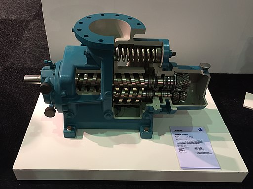
Construction of Screw Pump – Parts And Function
A screw pump with one screw is called single screw pump. The one with two screws are celled twin screw pumps; while the one with more than two screws are called multi screw pumps. Irrespective of their design variation and percentage share in overall application; a screw pumps can be classified into following key parts. The driver screw, driven screw, suction port, discharge port, rotary seal, dowel pin, stationary seal, ball bearing, cir clip, driving shaft and the timing gear.
1 ) Driver Screw
A driver screw is one of the rotating part of the screw pump; that helps pump the fluid at constant volumetric flow at any point of rotation. With driving shaft connected on one side and timing gear gear on another; it rotate with a close clearance with driven screw to push the fluid axially forward along the angle of rotation. A driver screw is basically a screwed spindle made of high tensile steel. The main role of driver screw in a screw pump is to drive the driven screw using a intermediate connection called timing gear.
The gentle axial movement of the screw along the low clearance with the driven screw helps create a low shear effect. This further improves the working life of the pump avoiding conditions such as; emulsification of fluid medium in case of water contamination and negative impact on other machinery connected in line.
2 ) Driven Screw
Made of same material as of driver screw; a driven screw rotates along its axis in effect of motion transmitted by timing gear. Unlike driver screw it rotates in the opposite direction with a fixed clearance area. This helps to trap water or any other fluid medium within the close clearance area. Now since both the screw spindles rotate in opposite direction without any change in clearance area; it move the fluid axially along the rotating angle to give non pulsating output.
To ensure the hydraulic balance along the pump central axis; both the driver and driven screw spindle have opposite screw direction. What i mean is; if the driver screw is of right hand type, the driven screw will be of left hand type and vice versa. Moreover for ideal running condition a driven screw takes much less; almost 1/12th to 1/14th of the total torque on driver screw.
3 ) Timing Gear
With both the driver ( male rotor ) and driven ( female rotor ) screw running with a very fine clearance; there is always a chance of contact. One such contact can wear the edge of the screw reducing the output pressure drastically. If remained unchecked it not only make pump uneconomical and far less efficient; but also trigger the screws to lock to each other in some cases. Thus a timing gear is installed on a screw pump to check such events.
The timing gear basically drives the driven gear in a way such; it does not lead to metal to metal contact between male and female rotor assembly. Furthermore it ensures that there is no such contact; even when the pump runs dry for a brief period of time. In three screw pump design with no timing gear; the outer two screws remains idle while the middle driver screw generate the axial fluid motion.
4 ) Suction & Discharge Ports
A screw pump has different suction and discharge ports as the fluid moves axially along the screw towards the discharge port. The suction and discharge ports are designed as such; it holds enough fluid medium when the pumps finally stops. This helps to provide initial fluid medium to the pump; avoiding it to run dry for a brief period of time even with empty or dry suction pipe. The suction port is subjected to partial vacuum condition; generated due to pressure difference between the suction port and the pump inlet.
This provide the much needed push to the fluid medium; to get trapped into different confined areas within thin screw clearance. On other hand the outlet is subjected to very high pressure; with the pump pushing even more fluid under all conditions. This is why the vorticity found at the discharge side of the pump is always higher than what at the suction port.
5 ) Relief Valve / Recirculation Line
Being a subset of positive displacement pump; a screw pump will produce pressure even with outlet shut. This can results into severe consequences; with loss of pump and connected machinery with damage to operating person. Thus to provide a sense of protection to the pump, connected machinery and operating person; all positives displacement pumps including this are equipped with relief valve. The other common method used to neutralize excess pressure is via outlet fluid re-circulation.
This can be achieved using a recirculating valve; that sends back part of the fluid at outlet back to the suction port via an internal passage. In many modern pump designs these relief valves came with an automatic flow control system; which maintains the output pressure and flow at any given point of time. They also came in handy reducing the starting torque for a screw pack subjected to back pressure at its outlet.
6 ) Bearings
In vertically mounted screw pumps the upper bearing is subjected to high load; along with radial and axial forces during pump operation. On other hand the lower bearings are subjected to very low load; with an important task to maintain the alignment of the pump components. In horizontally mounted screw pump both the sliding and roller bearings; are subjected to almost no ( Low ) load and forces due to pump action. It is so because the axial and radial forces generated oppose each other to nullify their effects.
Furthermore; in horizontally mounted pumps the bearing are submerged in the fluid medium. This lead to the creation of this thin film around; acting as a support structure for the pump assembly. At constant pressure the bearing loss or wear increase with increasing speed. Similarly at constant speed the rate of wearing loss decrease with increase in pressure. Generally a roller bearing is installed on the non drive side of the pump with drive or sliding bearing on another side.
7 ) Rotary and Stationary Seal
Screw pumps are fitted with a pair of mechanical seal with one on both side; to act as a sealing surface between the pumps dry side and the working liquid. This keeps the bearings and the timing gear separate on one side of the pump. While bearings and the shaft coupling separate on the other side. In many designs to ensure leak free sealing at suction; an additional gland packing is installed just after the mechanical seal to assist in the process.
Any mechanical seal with leakage more than 6 to 8 drops an hour should be immediately replaced with a new one. If remained unchecked the leakage will eventually grow quicker and quicker and damage the pump assembly. Care must be taken while replacing the mechanical gear; as any direct hand contact with the carbon sealing face can damage it.
8 ) Driving Shaft
It is the part of the pump that connects the pump assembly to its driving motor. This is achieved by using a proper set of flexible couplings. In many pump design a driving shaft is an integral part of the pump; running from one side to another holding drive screw onto it. In such designs these drive shaft are supported by a set of axially fitted bearings. To ensure prolonged life of the pump and its bearings it is require to properly align the pump shaft during pump installation.
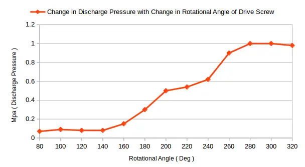
There is a general tendency of screw pump to see gradual increase in pump rpm and its pressure with increase in shaft power. On most designs shaft that connects the driving screw to the motor operation is made of mild steel.
Screw Pump Working Principle
A screw pump generates pressure by adding axial acceleration to the fluid medium within its fine clearance area. Unlike gear pumps with one gear driving the other; both driver and driven screws of the screw pump rotates in phase using timing gear. Both left and right hand screw running with a fine clearance; draws in air trapping within the fine clearance of inter meshing screw threads.
Pushing the air axially towards the output; it create differential pressure which helps suck in the fluid medium into pump medium. Now as the shaft rotates it push more and more fluid towards the outlet port with added pressure; due to axial acceleration of moving screw. The fluid can be trapped in between single or multiple screws depending upon pump design.
The best part is that the water sucked in moves from outside screw; towards their center of intersection within pump casing. So the water from all around moves towards the screw clearance; nullifying the effects of axial thrust providing hydraulic balance to pump assembly. This have three positive effects on pump performance; low output fluctuation, increased efficiency and increased bearing life.
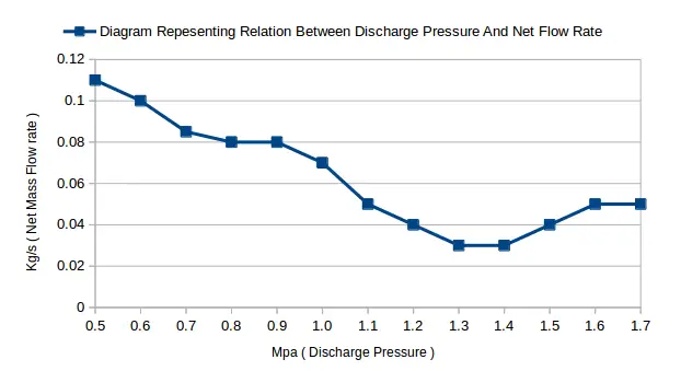
Due to its tendency to generate high vacuum pressure; it does not require priming and thus are self primed. These pump came with an rotational speed of 800 to 2600 rpm range in general. If we increase the rotational speed of the pump shaft; the output flow rate will increase drastically. While for an increase in output pressure the net flow rate decrease slightly.
Where Should We Use Screw Pump ?
While a screw pump can be used with almost any fluid medium; there are situation when it is more advantageous to use over others. A screw pump is best suited for application where we require non pulsating constant output; have medium with trapped air or gas; working with high viscous fluid, have low NPSH with the ability to withstand dry run for a short time interval.
It is also best choice when we require constant output flow even with varying back pressure. A screw pump is well known for its noise free operation even at high rpm and output pressure. It is a very versatile machine which provide the advantage of; high overall and volumetric efficiency reducing running cost of the pump operation.
They also provide the flexibility of controlled output, fewer vibrations, less maintenance; less shear and axial forces with an added advantage of no emulsification even with fluid containing traces of water. The only disadvantage why a screw pump is not used in many industries is its very high initial cost.
This makes it restricted to be used only where the other cheap alternatives; such as centrifugal and gear pumps does not perform well. So if you need to work with a variety of fluids with varying viscosity levels; one should go for screw pumps over others. Similarly if you need to keep constant output flow without emulsification of the medium; one should use screw pump.
Screw Pump – Maintenance and House Keeping
Even with the ability to withstand extreme running conditions; it do need maintenance and good housekeeping for prolonged operational life. A screw pump must never be run dry deliberately; as any dry run more than a minute or two can damage the pump parts. Care must be taken to avoid extreme pressure buildup due to output valve shut.
It is so because the recirculating valve in such condition ( 100% re-circulation ); can only withstand growing pressure for a period of four to five minute. Make sure that all the connections are lined up properly. What i mean is that; make sure the input and output pipelines are connected according to the plan. Ensure there is no leakage from the pump or connected pipelines.
Proper checks and maintenance must be done at regular interval of time; with time between two maintenance schedule not exceeding three years. Suction and delivery pressure must be monitored regularly with a quarterly need to clean pump strainers. A dirty or chocked suction strainer will lead to reduced suction pressure.
Similarly increased noise and vibration followed by a decrease in discharge pressure; is a clear cut indication of wear and tear in the pump internals. If too much air is being sucked in to the system leading to no or reduced discharge; increase the pump speed while sealing its suction port to rectify the condition. Now if you are struggling to get your screw pump self primed the remedy is to reverse the running direction; as a screw pump mostly won’t prime for incorrect direction of rotation.
Also Read:
- Standards For Marine Bunkering Hoses
- What is Ballasting And De-ballasting ? – Methods & Procedure
- How To Measure Wear Ring Clearance In Centrifugal Pump
- Why And How To Check Fuel Pump Timing in I.C Engine
- Parts Of Ship Its Definition And Their Function