
Last Updated on October 26, 2018 by Amit Abhishek
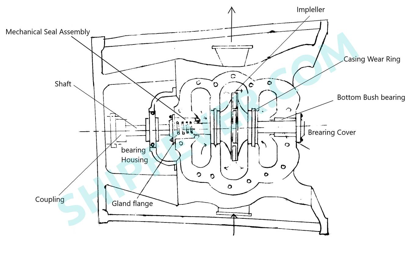
You must have read or heard about the term wear ring and its implication in centrifugal pumps; over and over again in schools, colleges and online course / articles. From its vary name one can know it is something which wear off. But wait a minute; is it safe for any part in centrifugal pump to wear off? A centrifugal pump consists of an impeller mounted on its shaft to pump low viscous liquid; such as water by the implication of centrifugal forces. Energy is transfered to the liquid upon the rotation of pump impeller. This exerts centrifugal force on the liquid pushing it outwards along the casing wall.
The volute casing wall converts this kinetic energy into pressure energy. Such energy conversion took place due to sudden increase in area before the pump discharge. The impeller is contained within the pump casing; where it rotate at an high rpm with a low clearance. As a result any deviation or misalignment of impeller or its shaft from its original position can damage the pump. Thus wearing rings are placed in between the casing and impeller. There are two such rings in an centrifugal pump which wear down in event of a contact to save the pump.
You might like to hold on a little and refresh your knowledge on centrifugal pump! If you have read the basics or too brilliant to skip; you must know that the efficiency of centrifugal pump is affected by its clearance area. The more is the clearance area more liquid will leak from discharge or high pressure side to the pump inlet. This negatively affects the overall pump efficiency increasing ranking cost per output volume. So a wear ring not just protect from any possible damage but also helps improve pump efficiency.
Effects Of Increase In Wear Ring Clearance On Centrifugal Pumps
A wear ring affects the working and performance of an centrifugal pump in a significant way. Centrifugal pumps with high wear ring clearance show an increase in its thrust and vibration. Uneven vibration can then further leads to loose bearings and contact between moving and stationary parts of the pump. As the clearance increase due to wear down;more and more fluid tends to backflow through the clearance reducing pump efficiency. Since the volume of water flowing through the space increase; the rate of cavitation increase too for the given clearance area.
Sudden increase in cavitation followed by decrease in pump efficiency make the pump rotor less stiff; reducing the rotor damping. It is being found in various test conducted on pumps; that there is more change in heat and low pressure area for the wear down of both rings than for just the rear one. It is the tendency of the centrifugal pump to expand its low pressure area; towards the volute with increase in clearance area. In the mean time the high pressure zone tends to move towards the pump inlet affecting natural working of the pump.
When a centrifugal pump undergoes negative effects such as reduced rotor damping, stiffness and efficiency along with increase in cavitation and vibration in general; the pump do require more and more power to operate with increased NPSH ( Net positive suction head ). This many a times makes the pump uneconomical for the industrial application. This is why a wear ring clearance is monitored time to time and replaced when needed.
Steps To Follow While Measuring Wear Ring Clearance
Measuring wear ring clearance is not as easy as it sounds. It require quite some effort, safety and a bit of experience and knowledge of how to use dial gauge and filler gauge for the measurement. To successfully conduct the measurement of wear ring clearance one need to follow the following steps; isolation, dismantling, Inspection, measurement and Reassembly.
1 ) Isolate
The key step of a pump isolation before dismantling is to cut off its power supply. Fuses are removed from the pump start panel to isolate power supply to the centrifugal pump. For additional safety main switch board breaker is turned off with a “Do not start” tag placed in the place. Additional signboard in the form of “MEN AT WORK” are placed at key places to alert crew or other workers of the ongoing work, maintenance or inspection.
Once the system itself is isolated; mark and remove electrical connections to the pump motor one by one. While you may or not be required to remove the pump from its motor assembly all together, but if you do; remove the couplings, bearings and shaft assembly of the motor to isolate pump to its motor. Generally just to measure wear ring clearance it is a common practice to skip this process altogether but is highly recommended.
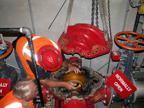
Now at last remove the bolts on the suction and discharge port flange to isolate pump from its connected lines. Crack open the pump drain to flush out any water / liquid remained in the pump to the bildge. Remove all connections including fluctuating line, instrumental connections, drain line and other accessories attached to the pump. Remove any coupling guard or spacer according to the pump design. At last connect the chain block shackle to the pump eye-bolt to lift the pump and place it on a secure position to inspect and dismantle.
2 ) Dismantle
It is nor required to dismantle whole pump assembly to measure wear ring clearance specially for a flat type wear ring. It can be done just by removing the cover of the pump in an axially mounted centrifugal pump. For some we might need to take out the impeller to measure the wear ring clearance; and for others he whole assembly is taken out and dismantled. Although as wear ring clearance is measured mostly as a part of preventive and break down maintenance; it is a common practice among, engineers, technician and pump operators to dismantle the whole assembly for inspection and measurement.
Bring essential spare parts such as gaskets, o-rings and ball or packing ring to replace it with the old once disassembled. You may or nor require to change other parts; such as wear ring after the inspection for damage, wear and tear. We need to remove the nuts from the gland bolts in order to remove the upper half of the pump casing. Don’t forget to turn down the jack-screw on the split flange; as it restrict lift off of the upper half and cause reassembly. Once done put an eye bolt on top and lift the upper half with the use of chain block and shackle.
Now, using slings around the shaft to lift the rotating part of the pump. Care must be taken while it is placed in secured place for further disassembly or wear ring measurement. For U and L type of wear rings remove the wearing covers, packing rings, lantern rings and the gasket along with stuffing box bushings; to remove the casing and impeller rings for inspection and measurement.
3 ) Inspect
Wear rings are inspected upon removing from pump assembly. Other than that; grub screw and shaft screws are to be cleaned and inspected for any sign of damage. Inspect the sealing ring, o-ring, shaft, key-way, impeller and lock nut for any sign of wear or damage. Give a clean blow to all parts of the pump to remove suspended particles and dust. Check for sign of impact pitting and corrosion on the impeller blades. Do appropriate maintenance when required but replace it with spare one when needed.
In some centrifugal pump’s you won’t find an impeller wear ring in the place. There is nothing to be panic or worry about as some design came with impeller; with in build wear surface as an integral part of impeller itself. In event of any confusion or doubt refer to instruction manual provided by the pump manufacturer. Check the condition of the surface before fitting new gland packing. Check for all bearings for damage and replace with new in respect to their running hours.
At last we need to check the diameter and alignment of the shaft and confirm its value with what given in manual provided by the manufacturer. Sometimes we also need to replace greasing nipple with a spare one based on its condition.
4 ) Measure
For plane wear ring we can take the wear ring clearance with or without dismantling major parts. All we need to do is to take out the upper half of the casing; and insert filler gauge in between the rotating and stationary part of the pump. You might need to take several attempt with different filler gauge size; to come up with the actual clearance. For other design such as L and U shaped wear ring; it is not feasible to take readings from filler gauge; and thus required to be taken out to measure the clearance.
Traditionally vernier caliper is used to measure the wear and new clearance of the wear rings. Take the wear rings out of the pump assembly and put on a flat clean surface. Now using a vernier caliper measure the internal and external diameter of the ring. Now match the value to that provided by the manufacturer. In the event you don’t have the required data or have lost it; compare it with data obtained from measuring a spare wear ring.
It is a common understanding to change the wear rings if its clearance become double of its original value. For more accurate measure we all must follow the measurement given by the manufacturer. As most people don’t want to dismantle the whole pump to check clearance even for the L and U type of wear rings. So they choose a shortcut method to know of the wear of these rings. to do that mount dial gauge on the impeller and using dial on the wear ring measure the deflection to check for signs of wear and tear.
5 ) Reassembly
At first assemble the pump impeller back on the pump shaft with all the wearing rings attached. Once they are assembled fix them to their place using the locking nut. Tighten the lock nut while sliding the shaft bush at the bottom. Apply some oil on the shaft surface and mechanical seal face before assembling. Now slowly slide the mechanical seal on to the shaft to its position and lock. Put bearings into its housing after applying light grease; then the whole housing is put back to its place sliding on the pump shaft. Once placed fix it in place using the lock nut or screw and put on the bearing cover.
Now assemble the shaft coupling and put pump rotor to its casing. Make sure to insert a new gasket in between the two halves. Join the shaft and its coupling to the motor assembly and tight it with a lock nut. Turn pump shaft with hand to check for free running clearance. In event of any interruption or non free movement; repeat all the above procedures from start. If it runs fine; convert the colling lines to the mechanical seal and bush. Connect all electrical connections to the motor with all connecting lines to the pump. Once done; start the pump and monitor its running current, vibration, leak, discharge pressure and suction pressure up to four to five minutes.
Note: This article is written and published on request of “Shamshad Ahmad“.
Also Read:
- Relay – Its Application, Parts And Function
- How Do Flywheel Work & Its function In I.C Engine
- Boiler Mountings And Their Function – Complete List
- What are BFP ( Boiler Feed Pump ) – Parts & Working
- Engine Cooling System – Types And Their Working
WHAT SHOULD BE CORRECT WEAR RING CLEARANCE FOR MAX PUMP EFFICIENCY
The correct Wear Ring Clearance setting For A centrifugal pump change with pump capacity and manufacturer. So ideally one should always refer to the manufacturer recommendation or company manual for the correct setting. But normally it is within the range of 0.025″ to 0.04″; with a feeler gauge of 0.030″ or 0.032″ used to check and achieve desired clearance.