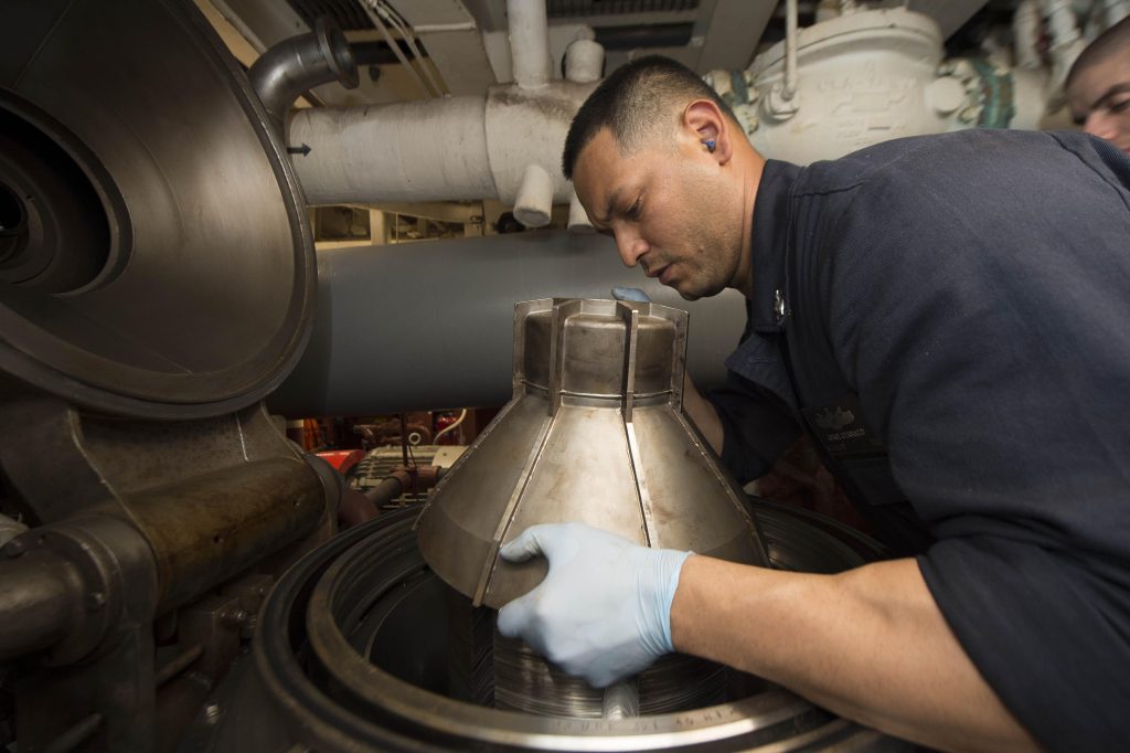
A high-speed centrifugal purifier is used on a ship to separate unwanted contaminants from lube and fuel oil. On the ship, we use separate marine purifiers for lube and fuel oil. While for lube oil only use centrifuge but for fuel oil, we use both centrifuge and gravity separation.
The gravity separation uses a settling tank for the process. The centrifugal purifier uses the principle of density difference to separate water and other contaminants from oil mixture.
While the separating force of these mixtures under gravity separation is defined by formula Fs = ∏/6*D3*(ρw-ρo)*g. Now by replacing gravity ( g ) with centrifugal force ω2 r we able to simply increases the rate of separation by a significant factor; making it a better way of purification.
What Are Purifiers And Why To Use Them On Ship
A purifier is an equipment with the sole purpose of purifying or cleaning the given media. On the ship, they are also referred to as Centrifuge ( equipment using centrifugal action to separate two medium ).
Marine fuel oil taken from bunker contains solid contaminants such as ash, carbon, cat fines and dust that if remained unchecked will accelerate normal wear and tear damaging cylinder liner, piston, piston rings and fuel injector.
Further we have water particles in the bunker fuel. Which if remained unchecked will assist in chemical reaction between vanadium and sodium forming sticky liquid salts during combustion process.
It may also leads to situation such as cavitation of injectors, microbial formation, ignition delays and subsequent reduction in quality of oil.
After receiving the fuel oil in bunker tank we transfer them to first storage tanks and then to settling tanks where the heavier contaminants and water gets separated under the effect of heat.
The fuel is then further purified using a centrifugal purifier to remove sludge, water, and solid contaminants completely.
Difference Between Centrifugal Purifier And Clarifier
Centrifugal Purifier | Centrifugal Clarifier |
It is a type of centrifuge that can separate two liquid substances based on their difference in density. | It is a type of centrifuge that can only separate solid contaminant from a liquid medium. |
Gravity disc is used and thus separates both solid and water. | No gravity disc in the system. Thus it only separates solid contaminants. |
Sealing water is required for operation. | No such requirement of sealing water. |
Lower discs have holes and have two outputs at the top; one for water and other oil. | The lower disc has no holes and there is just one outlet at the top for oil. |
It Can or cannot be used in a series of centrifugal purifiers. | Can only be used in series with a centrifugal purifier on ship due to presence of water. |
Construction Features of Centrifugal Purifier
A centrifugal purifier consists of various parts such as the bowl, disc stack, gravity disc, electric motor, inlet-outlet ports, rotating shaft, friction pads, shafts, gearbox, and automation devices.
Electric motor
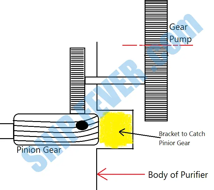
A purifier consists of an electric motor which drives the various component, such as Bowl, Nodge(rotating counter), Tachometer, Gear-pump(via pinion gear)
Friction Clutch
The complete purifier assembly is too heavy for a motor to take the full load from start without overheating. Thus to safeguard and protect the electric motor from damage friction clutch are installed on the horizontal shaft.
These pads gradually move out under centrifugal force connecting the motor directly to the bowl once the system attends a preset required momentum. To start the revolution of the Bowl, it is necessary that the Friction clutch engage with the Drum.
It acts as a safeguard against heavy starting current. If there would have been a solid coupling, then due to a large starting current the winding of the motor will simply overheat and burn.
So friction coupling allows for some time, and after certain R.P.M is being achieved by the motor the coupling gets engaged.
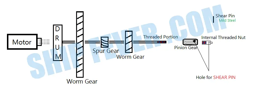
The Gear Box
The gearbox assembly in a centrifugal purifier consists of a motor shaft, friction clutch, the breaking lever, spur gear, worm gear, and attached gear pump.
The Bowl & Disc Stack
The bowl is a solid assembly that operates within the purifier frame made of high tensile steel with ample space to accumulate and discharge sludge.
Purifier and clarifier bowls have conical disc stack, which may be numbered from 150 to 200 and are separated from each other by a small gap.
Small holes are provided on these disc stacks where the interference line is formed and separation takes place. The centrifugal force cause oil to move inward and water and solid particle to move outward.
Rotating Shaft & Automation
The bowl is driven by an electric motor using bevel gear to produce centrifugal action. The vertical shaft rotated the bowl at high speed and is connected with horizontal shaft using a spur gear.
The horizontal shaft is driven directly by the electric motor through a clutch plate or friction plate. Apart from other mechanical devices a centrifuge also have an automation circuit consist of transducers, monitor, detectors, solenoid valve and control panel.
Gravity Disc & Pairing Discs
Also known as the damn ring it is fitted on top of the disc stack to create an oil-water interface based on density difference. It is another disc fitted at the neck of the bowl converting rotational energy into pressure energy.
Centrifugal Purifier Working Principle
The dirty oil is supplied to the center from the settling tank. Then due to centrifugal force, the separation between oil and water took place due to their different density.
Water being heavier than oil is thrown out toward the wall of the bowl whereas the oil is positioned in the center. Water is applied first, because if the oil is supplied directly to the purifier, it will come out from the waterside, so water is supplied first and it is checked that it is coming from the waterside, gradually the seal water is shut off.
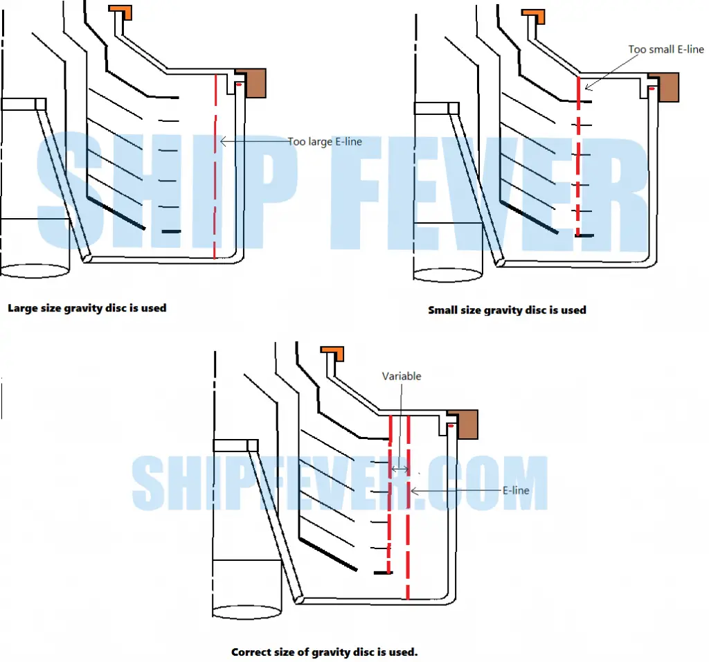
If we supply seal water quickly, it may come to the oil side. An interference line is formed between Water and oil, this line is also known as E-line.
The position of this interface within the purifier is very important for correct operation, this interface is achieved by gravity disk at the outlet.
A number of gravity disc is provided with the purifier. This Gravity disk (a.k.a Regulating Ring) that is used has a different diameter for the different density of oil to be purified, so if the oil is being changed the gravity disk has to be changed.
As a thumb rule, a large-diameter gravity disk that does not break the seal should be used. A blind disc is at the top disc stack.
Maintenance procedure
- Particular care should be taken when moving the main bowl parts so to avoid damage to the sealing faces and prior opening it must be ensured that the purifier is a complete stop and not rotating.
- All seals to be renewed.
- Clutch drive to be checked and lining renewed if required.
- Gearbox to be checked for abnormal wear. Bearing to be within makers running period limit. Gearcase lubricating oil to be renewed.
- Prior to reassembly all sliding faces to be suitably lubricated. Bowl height to be measured and adjusted according to makers limits. Record to be taken.
- Before closing top cover, turn the bowl by hand. To test if it’s free of obstruction.
- After running up to normal speed the operation of the purifier shall be checked especially the separating efficiency of the purifier with regard to the selection of the correct gravity disc or plug.
- Correct torque should be employed as mentioned by the maker.
- Necessary entries shall be made in the record.
A centrifuge is a perfectly dynamically balanced piece of equipment with very high R.P.M, so the care should be taken while dismantling and boxing it up and also during maintenance.
***Always refer to maker manual before carrying out any maintenance***
Also Read:
- What are The Alarms and Trips of the Inert Gas System?
- Effects Of Poor Residual Fuel On Marine Diesel Engine?
- Oily Water Separator Construction Working & Dismantling
- Lube Oil Properties To Consider For Marine Engine
I need to know good purification principl. How can i understand that my purifier is woriking good conditio?
The most common method used by us engineers is to take a note of sudden or gradual increase in change in oil filters. If there is a sudden increase in oil filter change overs, reduced oil quality and change in purifier running parameters; there is a clear indication that the purifier is not in good condition and need to be overhauled. But most of the time we stick to the planned maintenance schedule on purifiers which prevent from such sudden problems in purifiers.
Why is it necessary to maintain the temperature of 98deg.cel when purifying heavy fuel oil?
Increasing the temperature of the working medium in a purifier help with its purification. The higher the temperature the better and efficient will be the separation of sludge and suspended particles from clean oil. Furthermore, if the temperature is kept too low it may lead to poor flow rate or even wax formation.
Fundamentally it is the viscosity that needs to be reduced to enable flow of the liquid. That is why higher the viscosity the higher the separation temperature. Residual fuels (Heavy Oil) with 380 or 180 cst would need about 98 degrees C heating. However, Diesel Oil (MDO) with viscosity less than 14cst would need 40 degrees c. Lub Oil from Cross Head Engines would need 90 degrees heating while Lub Oil for Trunk Piston engines would need 95 degrees Separation temperature.
Comment…How to adjust purifier bowl height
The relative height of the bowl is adjusted by changing or replacing the bowl shim with of different thickness.
What are the soals regulations for purifier?
Why is it important to adjust bowl height according manufacturer’s standard?
It is because if the bowl height is too less than recommended; oil will pass through the water lines. While if it is too much it does not purify properly.
What is Purifier speed and What is Purifier motor speed?
Usually the RPM of motors is less than the RPM of PURIFIER. For example if the rpm of motor is 1300 then the rpm of purifier could be 3500. As purifier rotates faster than the motor.
The speed with which the purifier runs is around 5000-7000 rpm and the motor with which the purifier takes the speed of rotation runs around 14000-15000 rpm to control the speed range we use worm gears attached in the horizontal shaft.
Good day,sir. In my exam, they asked me, what is the speed of vertical shaft of purifier.? Sir, I don’t get the answer anywhere. Could you plz tell me,sir.?
The RPM of the motor shaft ( horizontal shaft ) of the purifier is same as that of the motor while the vertical shaft speed depends upon the gear ratio.
Thank you, sir. But they gave me options like 16000, 8000, 1500 & 10000… Among theses which one is possible speed of vertical shaft, sir.?
I didn’t get the answer anywhere, sir.
10000
Could you please tell me, what will be the reasons for an observed defect in making of water wall in ALFA LAVAL, MAPX-204TGT-24/60/4139-6 Fuel oil purifier.
Defective operating water mechanism/Not enough pressure in the water line due to clogging.
what are the factors that affect marine fuel oil purification?
Temperature, Density and quantity of water and impurities.